Engine Out
To assist overhaul of the engine and cleaning and painting of the chassis and front suspension the engine had to come out. Given the wear and loss of compression, it's a wonder the engine runs as well as it does, just another of the strengths of the Gardner design.

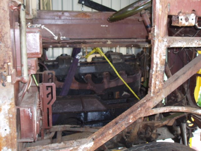
THROUGH THE CAB DOOR SHOWING ALL PANELS AND THE FLOOR REMOVED, AND THE SLINGS IN PLACE TO TAKE THE STRAIN
Craig had unbolted the gearbox from its clutch housing and lowered it to the floor on the previous weekend. In spare moments he had also stripped all the external panels from the cab, removed the cab floor and dismantled the gear shift housing from its mounting on the side of the engine crankcase.

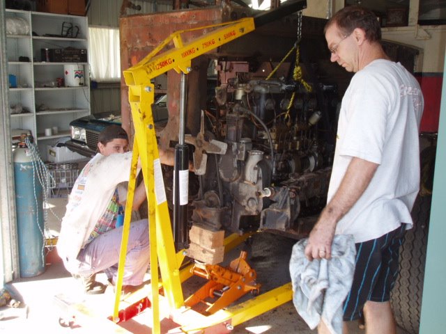
THE WEIGHT HAS BEEN TAKEN: THE HOIST HAS NOT FOLDED AND THE SLINGS HAVE NOT SNAPPED
So all we had to do was take the weight of the engine on slings from a cantilever engine hoist. But Craig had had a heavy work week with no spare time, so first thing was a trip down the Princes Highway to Dapto to Pete's place to collect the hoist.
The hoist (see picture) is a heavy steel bar, extendable by a metre or so horizontally, and raised by a hydraulic ram. But each extension loses you about 250 kg in safe lifting capacity, and the Gardner is a very long engine, so by the time we had the hook over engine centre, the SWL was 750 kg. Oh well, in for a penny in for a pound, suck it and see, give it a whirl and all that.

THE FIRST SIX INCHES OF THE MOVE FORWARDS OUT OF THE CHASSIS. SO FAR, SO GOOD. THE JIB OF THE HOIST CAN BE SEEN TO BE AT FULL EXTENSION
And slinging the engine posed problems with the gear we had to hand. We estimated the engine minus gearbox weighed about 800 kg. The Gardner workshop manual very wisely suggests using two eyebolts screwed onto specially extended cylinder head studs as lifting points, but lacking these with their peculiar British Standard Fine threads we had to improvise.
We did not want to use chains which would bear against the cast aluminium sump and risk cracking it, so what soft nylon straps we could locate were obtained. One of these was only a metre long and despite some head scratching to try combining it with chains to get length, it was abandoned in favour of a nylon towing rope of presumably at least a ton capacity. Craig's friend Ian, from Morris Mini restoration days, turned up to help and was a tower of strength. Three heads are better than two.
Straps and ropes were carefully arranged to avoid crushing pipework or delicate aluminium alloy auxiliaries, and the hoist raised to take the strain. Everything held: the front tubular crossmember bolts were taken out, and the rather complex pivoting rear engine mounts had to be partly dismantled to release them.

IAN AND CRAIG KNOCK THE TUBULAR FRONT CROSS MEMBER DOWNWARDS TO REMOVE IT FROM BETWEEN THE CHASSIS RAILS. THOSE WHO HAVE SEEN A POST WAR CX19 WILL NOTE THAT THIS CROSS MEMBER IS DIFFERENT, TO SUIT THE LOWER FRONT ENGINE MOUNT OF THE GARDNER
The engine is not mounted on the centre line of the chassis: as in all double deckers it is angled to the nearside, so the drive line passes under the row of seats on the kerb side of the bus, giving a lower floor at the centre corridor. So the nearside mounting gets tangled up with the chassis cross member under the engine firewall, necessitating removal of many bolts and pins to free it up. Luckily these were made to be quite accessible, and came apart easily despite having been untouched for 40 years or so.

THE MAGIC MOMENT: THE ENGINE COMES CLEAR OF THE CHASSIS AND ALL THE VARIOUS PROTRUSIONS, INCLUDING THE RADIATOR SUPPORT STUD, LOWER CENTRE OF PICTURE
By now the engine was dangling from its straps and we gingerly dragged the hoist forward, lifting it to clear the front axle, lowering it to clear the radiator mounting brackets and removing protruding pieces of cab and engine to enable forward progress. By mid afternoon it was all clear and it all seemed to have been quite easy, didn't it? With the Gardner manual in one hand and the engine exposed to easy scrutiny, we looked for the magic letter 'S' stamped on the rear of the crankcase to indicate it is a Type 3, with copper-lead slipper bearings. Earlier engines have cast babbit metal bearings which require skilled hand scraping to get a perfect fit. No 'S' --- but removal of sump will reveal all.

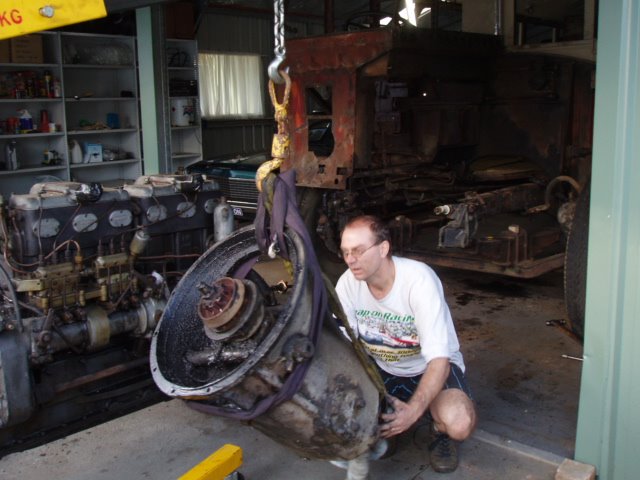
THE GEARBOX ON THE HOIST COMES CLEAR OF THE FRONT AXLE. IAN LOOKS RELIEVED
Now we could use the hoist to drag the gearbox forward and lift it out over the front axle. The opportunity was used to take its top cover off.
Two major surprises emerged: all the gears were in beautiful condition, apart from the expected minor chipping at the front of the second speed wheel, caused by drivers changing down to second on steep hills and not timing it 100%, and by engaging second roughly when taking off from a stop.


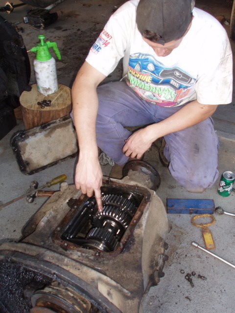
CRAIG POINTS TO THE ONLY VISIBLE WEAR IN THE GEARBOX, ON THE FRONT OF THE SECOND SPEED WHEEL. THE CLEAN GLOW FROM WITHIN THE GEARBOX IS VERY ENCOURAGING
Everything inside shone like polished silver, but to my great surprise, there were no helical teeth on any gears! My theory was that early prewar buses had silent third gearboxes with this feature abandoned on later versions. So maybe 1615 got a post war box in its career (quite likely) or my theory is rubbish (very likely). The intriguing thing is that elsewhere we actually have such a box, with helical gears, so its origins are a matter of some interest. Your comments on this mystery, please.

THE VOID LEFT IN THE ENGINE BAY LOOKS RATHER SAD, BUT SHOT BLASTING AND PAINTING WILL CHANGE ALL THAT.
THROUGH THE CAB DOOR SHOWING ALL PANELS AND THE FLOOR REMOVED, AND THE SLINGS IN PLACE TO TAKE THE STRAIN
Craig had unbolted the gearbox from its clutch housing and lowered it to the floor on the previous weekend. In spare moments he had also stripped all the external panels from the cab, removed the cab floor and dismantled the gear shift housing from its mounting on the side of the engine crankcase.

THE WEIGHT HAS BEEN TAKEN: THE HOIST HAS NOT FOLDED AND THE SLINGS HAVE NOT SNAPPED
So all we had to do was take the weight of the engine on slings from a cantilever engine hoist. But Craig had had a heavy work week with no spare time, so first thing was a trip down the Princes Highway to Dapto to Pete's place to collect the hoist.
The hoist (see picture) is a heavy steel bar, extendable by a metre or so horizontally, and raised by a hydraulic ram. But each extension loses you about 250 kg in safe lifting capacity, and the Gardner is a very long engine, so by the time we had the hook over engine centre, the SWL was 750 kg. Oh well, in for a penny in for a pound, suck it and see, give it a whirl and all that.
THE FIRST SIX INCHES OF THE MOVE FORWARDS OUT OF THE CHASSIS. SO FAR, SO GOOD. THE JIB OF THE HOIST CAN BE SEEN TO BE AT FULL EXTENSION
And slinging the engine posed problems with the gear we had to hand. We estimated the engine minus gearbox weighed about 800 kg. The Gardner workshop manual very wisely suggests using two eyebolts screwed onto specially extended cylinder head studs as lifting points, but lacking these with their peculiar British Standard Fine threads we had to improvise.
We did not want to use chains which would bear against the cast aluminium sump and risk cracking it, so what soft nylon straps we could locate were obtained. One of these was only a metre long and despite some head scratching to try combining it with chains to get length, it was abandoned in favour of a nylon towing rope of presumably at least a ton capacity. Craig's friend Ian, from Morris Mini restoration days, turned up to help and was a tower of strength. Three heads are better than two.
Straps and ropes were carefully arranged to avoid crushing pipework or delicate aluminium alloy auxiliaries, and the hoist raised to take the strain. Everything held: the front tubular crossmember bolts were taken out, and the rather complex pivoting rear engine mounts had to be partly dismantled to release them.

IAN AND CRAIG KNOCK THE TUBULAR FRONT CROSS MEMBER DOWNWARDS TO REMOVE IT FROM BETWEEN THE CHASSIS RAILS. THOSE WHO HAVE SEEN A POST WAR CX19 WILL NOTE THAT THIS CROSS MEMBER IS DIFFERENT, TO SUIT THE LOWER FRONT ENGINE MOUNT OF THE GARDNER
The engine is not mounted on the centre line of the chassis: as in all double deckers it is angled to the nearside, so the drive line passes under the row of seats on the kerb side of the bus, giving a lower floor at the centre corridor. So the nearside mounting gets tangled up with the chassis cross member under the engine firewall, necessitating removal of many bolts and pins to free it up. Luckily these were made to be quite accessible, and came apart easily despite having been untouched for 40 years or so.
THE MAGIC MOMENT: THE ENGINE COMES CLEAR OF THE CHASSIS AND ALL THE VARIOUS PROTRUSIONS, INCLUDING THE RADIATOR SUPPORT STUD, LOWER CENTRE OF PICTURE
By now the engine was dangling from its straps and we gingerly dragged the hoist forward, lifting it to clear the front axle, lowering it to clear the radiator mounting brackets and removing protruding pieces of cab and engine to enable forward progress. By mid afternoon it was all clear and it all seemed to have been quite easy, didn't it? With the Gardner manual in one hand and the engine exposed to easy scrutiny, we looked for the magic letter 'S' stamped on the rear of the crankcase to indicate it is a Type 3, with copper-lead slipper bearings. Earlier engines have cast babbit metal bearings which require skilled hand scraping to get a perfect fit. No 'S' --- but removal of sump will reveal all.

THE GEARBOX ON THE HOIST COMES CLEAR OF THE FRONT AXLE. IAN LOOKS RELIEVED
Now we could use the hoist to drag the gearbox forward and lift it out over the front axle. The opportunity was used to take its top cover off.
Two major surprises emerged: all the gears were in beautiful condition, apart from the expected minor chipping at the front of the second speed wheel, caused by drivers changing down to second on steep hills and not timing it 100%, and by engaging second roughly when taking off from a stop.
CRAIG POINTS TO THE ONLY VISIBLE WEAR IN THE GEARBOX, ON THE FRONT OF THE SECOND SPEED WHEEL. THE CLEAN GLOW FROM WITHIN THE GEARBOX IS VERY ENCOURAGING
Everything inside shone like polished silver, but to my great surprise, there were no helical teeth on any gears! My theory was that early prewar buses had silent third gearboxes with this feature abandoned on later versions. So maybe 1615 got a post war box in its career (quite likely) or my theory is rubbish (very likely). The intriguing thing is that elsewhere we actually have such a box, with helical gears, so its origins are a matter of some interest. Your comments on this mystery, please.
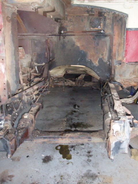
THE VOID LEFT IN THE ENGINE BAY LOOKS RATHER SAD, BUT SHOT BLASTING AND PAINTING WILL CHANGE ALL THAT.
posted by Pennie at 10:40 AM
1 comments
![]()
![]()

