Decision: the Bottom Deck Gets a New Frame
What with my time being pretty fully committed to getting Leyland TD4 no. 1579 ready for the big day out at Motorfest on Australia Day, and Craig working strange and long hours on the railway, not a lot has changed with m/o 1615 since the last blog entry.
However there has been activity: much further dismantling has made it possible to extract pillars and roof bows in order to find a good example of each to use as a template for the bending of new ones. This involved completely removing the floor of the top deck, which is in fact the roof of the bottom deck; hundreds of woodscrews and many tongued and grooved oregon planks, mostly rotted at one end or both, or along the sides.
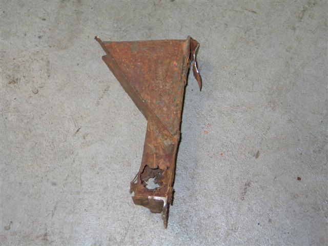
In the event Craig found it impossible to unpick the whole of the welded junction of a floor cross member to a vertical pillar in order to obtain a complete example of a pillar to use as a template. Something had to give: either the floor bearer or the pillar would be damaged. As the floor bearers are actually in quite good condition, it was the pillar which had to suffer.

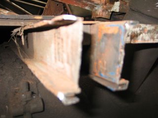
THE DETAIL OF THE JUNCTION OF VERTICAL PILLAR (at right) AND A FLOOR CROSS MEMBER. THE TRIANGULAR GUSSETS MAKE THE JOINT IMMENSELY STRONG BUT ADD TO THE DIFFICULTY OF DISMANTLING IT. Something has to stop the body slumping sideways during cornering, and these gussets are a major part of it. In addition, the bulkheads at front and rear of the bottom deck incorporate massive amounts of diagonal bracing.
THE VIEW ACROSS A LOWER DECK CROSS MEMBER AT FLOOR LEVEL. THE VERTICAL PILLAR HAS BEEN CUT OUT, LEAVING WHAT APPEARS TO BE A PERFECT FLOOR BEARER, READY TO HAVE THE NEW PILLAR SLOTTED IN AND GUSSETS ADDED.

THE SAME BEARER FROM A HIGHER VIEWPOINT. The entire weight of bottom deck, top deck, body and passengers is borne at seven such points on each side of the bus.
The angle iron rail heading diagonally at top right is part of the battery box: pre-war deckers had the batteries under the nearside front floor, a bit harder to get at, but closer to where they are needed, ie the starter motor.

LOOKING ALONG THE OFFSIDE TOWARDS THE FRONT. THE DRIVER'S CAB HAS GONE, CUT OUT BECAUSE NO ONE PART OF IT WAS REALLY GOOD ENOUGH TO KEEP. The front scuttle had suffered an impact at some stage and was distorted inwards, and all the other horizontal and vertical frame members, plus the cantilever rail at the top of the cab side, would have needed rust cut out and patches inserted, such that it will be quicker to make new ones.
A firm at Silverwater has been found who specialise in shaping and bending of steel sections. They can supply exactly the sizes we want and curve them to our needs.
It may then be possible to fabricate one entire side of the body, fit it to the existing floor bearers and then put the roof bows in place to hold it all together..

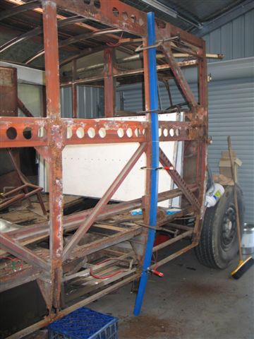
THE BLUE PIECE IS A LENGTH OF 50mmX50mm STEEL BOX SECTION (RHS: rectangular hollow section) which has been cut at regular intervals part way through with a fine cutting disc in the angle grinder so that it will curve to the shape of an existing pillar. Then, solidly clamped to the pillar, the cuts will be welded up so that a rigid curved section results, to be used as a template for four such pillars. The 50x50 pillars are used at either side of the front bulkhead and the rear bulkhead, which forms the front wall of the rear platform. The other ten pillars, at the intermediate points along each side, are 45mmx45mm sections.
Those of you in the know will say: "Ah, but those pillars should be a top-hat section, not square..." So, having curved the pillars and bows to shape, they will have a flat strip welded to one side to provide the flange, which is necessary in certain places, especially along the sides where windows and pillar covers are held in place.
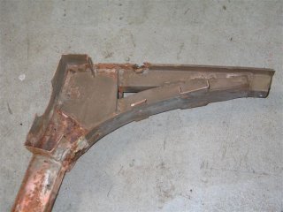
AT THE TOP OF EACH PILLAR THERE IS A FAIRLY COMPLEX JOINT TO THE ROOF BOW cum TOP DECK FLOOR BEARER. MOST OF THESE JOINTS HAVE SUFFERED SEVERE RUST, SO WILL ALL BE REPLACED. THIS VIEW SHOWS THE PILLAR AT LEFT, AND THE ROOF BOW AT TOP. THIS EXAMPLE IS THE BEST SURVIVING, AND WILL BE USED AS THE PATTERN FOR NEW ONES.
In the event, it was found later that the curved section forming the brace between bow and pillar was a very clever folded and rolled channel, embracing the two sections with the pentagonal bits acting as strengthening. Making the brace is beyond the scope of our skills and tools, so we will resort to an earlier method, used in 1937 production of these bodies, which used flat gussets and a curved plate to achieve the same thing.

A COMPLETE ROOF BOW, EXTRACTED IN ONE PIECE TO BE USED AS THE TEMPLATE. ONCE AGAIN THE BEST SURVIVING ONE OF ITS KIND. NOTE HOW LIGHT IT APPEARS, YET IT AND SIX OTHERS SUPPORT 16 SEATS AND THE WEIGHT OF 33 SEATED PASSENGERS. SOMEHOW THE ORIGINAL BUILDERS, WADDINGTON'S, MANAGED TO BUILD IN A TIGHT-FITTING WOOD INSERT, WHICH TAKES THE SCREWS HOLDING DOWN THE FLOOR BOARDS, PASSING THROUGH THE ONE INCH DIAMETER HOLES. Presumably the wood was sawn to the curve and slid in from one end before welding commenced; could be interesting.
However there has been activity: much further dismantling has made it possible to extract pillars and roof bows in order to find a good example of each to use as a template for the bending of new ones. This involved completely removing the floor of the top deck, which is in fact the roof of the bottom deck; hundreds of woodscrews and many tongued and grooved oregon planks, mostly rotted at one end or both, or along the sides.
In the event Craig found it impossible to unpick the whole of the welded junction of a floor cross member to a vertical pillar in order to obtain a complete example of a pillar to use as a template. Something had to give: either the floor bearer or the pillar would be damaged. As the floor bearers are actually in quite good condition, it was the pillar which had to suffer.
THE DETAIL OF THE JUNCTION OF VERTICAL PILLAR (at right) AND A FLOOR CROSS MEMBER. THE TRIANGULAR GUSSETS MAKE THE JOINT IMMENSELY STRONG BUT ADD TO THE DIFFICULTY OF DISMANTLING IT. Something has to stop the body slumping sideways during cornering, and these gussets are a major part of it. In addition, the bulkheads at front and rear of the bottom deck incorporate massive amounts of diagonal bracing.

THE VIEW ACROSS A LOWER DECK CROSS MEMBER AT FLOOR LEVEL. THE VERTICAL PILLAR HAS BEEN CUT OUT, LEAVING WHAT APPEARS TO BE A PERFECT FLOOR BEARER, READY TO HAVE THE NEW PILLAR SLOTTED IN AND GUSSETS ADDED.
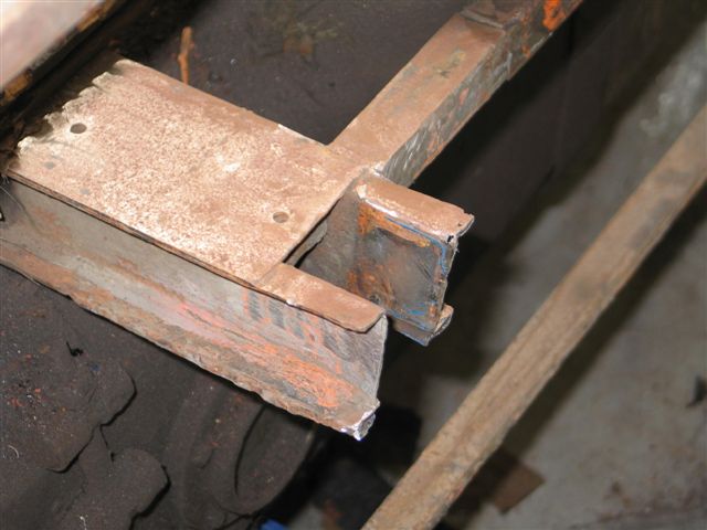
THE SAME BEARER FROM A HIGHER VIEWPOINT. The entire weight of bottom deck, top deck, body and passengers is borne at seven such points on each side of the bus.
The angle iron rail heading diagonally at top right is part of the battery box: pre-war deckers had the batteries under the nearside front floor, a bit harder to get at, but closer to where they are needed, ie the starter motor.
LOOKING ALONG THE OFFSIDE TOWARDS THE FRONT. THE DRIVER'S CAB HAS GONE, CUT OUT BECAUSE NO ONE PART OF IT WAS REALLY GOOD ENOUGH TO KEEP. The front scuttle had suffered an impact at some stage and was distorted inwards, and all the other horizontal and vertical frame members, plus the cantilever rail at the top of the cab side, would have needed rust cut out and patches inserted, such that it will be quicker to make new ones.
A firm at Silverwater has been found who specialise in shaping and bending of steel sections. They can supply exactly the sizes we want and curve them to our needs.
It may then be possible to fabricate one entire side of the body, fit it to the existing floor bearers and then put the roof bows in place to hold it all together..

THE BLUE PIECE IS A LENGTH OF 50mmX50mm STEEL BOX SECTION (RHS: rectangular hollow section) which has been cut at regular intervals part way through with a fine cutting disc in the angle grinder so that it will curve to the shape of an existing pillar. Then, solidly clamped to the pillar, the cuts will be welded up so that a rigid curved section results, to be used as a template for four such pillars. The 50x50 pillars are used at either side of the front bulkhead and the rear bulkhead, which forms the front wall of the rear platform. The other ten pillars, at the intermediate points along each side, are 45mmx45mm sections.
Those of you in the know will say: "Ah, but those pillars should be a top-hat section, not square..." So, having curved the pillars and bows to shape, they will have a flat strip welded to one side to provide the flange, which is necessary in certain places, especially along the sides where windows and pillar covers are held in place.

AT THE TOP OF EACH PILLAR THERE IS A FAIRLY COMPLEX JOINT TO THE ROOF BOW cum TOP DECK FLOOR BEARER. MOST OF THESE JOINTS HAVE SUFFERED SEVERE RUST, SO WILL ALL BE REPLACED. THIS VIEW SHOWS THE PILLAR AT LEFT, AND THE ROOF BOW AT TOP. THIS EXAMPLE IS THE BEST SURVIVING, AND WILL BE USED AS THE PATTERN FOR NEW ONES.
In the event, it was found later that the curved section forming the brace between bow and pillar was a very clever folded and rolled channel, embracing the two sections with the pentagonal bits acting as strengthening. Making the brace is beyond the scope of our skills and tools, so we will resort to an earlier method, used in 1937 production of these bodies, which used flat gussets and a curved plate to achieve the same thing.

A COMPLETE ROOF BOW, EXTRACTED IN ONE PIECE TO BE USED AS THE TEMPLATE. ONCE AGAIN THE BEST SURVIVING ONE OF ITS KIND. NOTE HOW LIGHT IT APPEARS, YET IT AND SIX OTHERS SUPPORT 16 SEATS AND THE WEIGHT OF 33 SEATED PASSENGERS. SOMEHOW THE ORIGINAL BUILDERS, WADDINGTON'S, MANAGED TO BUILD IN A TIGHT-FITTING WOOD INSERT, WHICH TAKES THE SCREWS HOLDING DOWN THE FLOOR BOARDS, PASSING THROUGH THE ONE INCH DIAMETER HOLES. Presumably the wood was sawn to the curve and slid in from one end before welding commenced; could be interesting.
posted by Pennie at 9:41 PM
0 comments
![]()
![]()

